
Tilton Cooler Pump - Standard Fluid - Intermittent Use
$499.00
or 4 payments of $124.75 with
 Learn more
NEED HELP?


SKU code: 40-525
or 4 payments of $124.75 with
Learn more
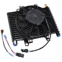
Take your vehicle's performance to the next level with the 12V Oil Pump Viton with Bypass Tilton-a high performance, self-priming pump for racing applications. This pump pumps oil through transmission and differential coolers for maximum lubrication and cooling in extreme conditions. 1-2 GPM flow rate, 60 PSI max working pressure and built in bypass valve for consistent and reliable performance.
Tilton cooler pumps are trusted by race teams and performance enthusiasts for efficient oil circulation which is critical for temperature control in high performance engines. The self-priming design allows for easy installation even when mounted 8 feet above the fluid source so you have flexibility in placement.
The Viton model is designed for use with corrosive fluids like alcohol making it perfect for motorsport applications that demand durability and chemical resistance. Unlike standard oil pumps the Tilton 12V Oil Pump with Viton seals is built for high performance vehicles and race applications where oil flow consistency and reliability are key. Whether used in transmissions, differentials or cooling systems this pump ensures optimal oil transfer for increased engine longevity and efficiency.
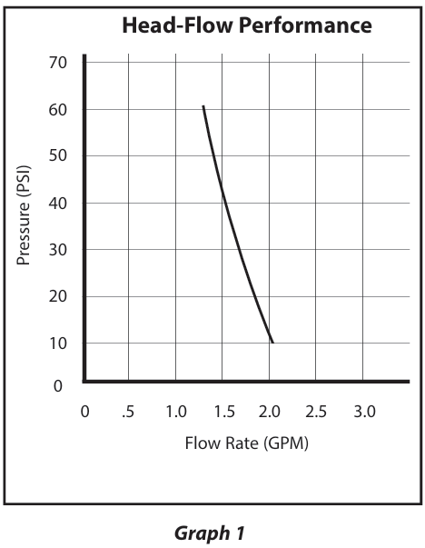
The Tilton Differential Pump is a positive displacement type of pump, so its output is directly proportional to the motor speed. If a lighter load increases the motor speed by 25%, then the flow rate increases by 25%. The flow rate vs. pressure is shown in Graph 1 with a maximum available pressure of 60 PSI. A fluid system will only flow as much as the smallest restriction will allow. Larger diameter lines and fittings allow more flow and place less load on the pump. This pump is self-priming and can be placed up to 8 ft above the source from which it draws. The typical application for the pump is in a differential or transmission cooling system. However, the pump can be used for other applications such as emptying fuel tanks. A 12-volt DC, 10-amp power supply is required. The current draw is 6.6 amps under a maximum load condition with a more typical current draw between 2 and 3 amps. This pump has a very light weight at 3.5 lbs and has a flow rate of 1-2 gallons per minute. There are two types of diaphragms available for the differential pumps; the BUNA type diaphragms are for standard coolants and the VITON diaphragms are for the more
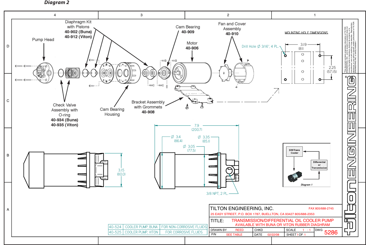
The Tilton Differential Pump is placed inline with the cooling system as shown in Diagram 1. Placing the pump on the outlet side of the cooler exposes it to lower temperatures significantly increasing the life and reliability of the pump. A filter placed inline before the inlet of the pump prevents foreign objects from damaging the pump. Heavy gear oil must be brought up to operating temperature before the pump is engaged. The cold fluid can be very thick and place an unusually large strain on the pump. Tilton recommends the use of an on/off switch so the pump can be turned off during warm-up periods. The pump includes an integral cooling fan to keep the pump cool during loaded conditions. If the pump is mounted in a vertical position, mount the pump with the motor above the pump inlet and outlet to prevent damage to the motor in the event of a fluid leak. The pump head can be rotated in 180-degree increments, allowing a variety of hose positions. Be careful not to damage the plastic pump housing by over tightening the fittings. If a check valve is placed inline with the pump, the check valve must have an opening pressure of no more than 2 PSI. The electrical hook-up is simple. Connect the pump to a 12-volt DC supply with a 10-amp fuse inline with the (red) positive lead. The black lead is the chassis ground.
| Symptom | Possible Causes | Action to Take |
|---|---|---|
| Motor runs, no discharge | Restricted intake or discharge lines | Check for restrictions |
| Air leak in intake line | Check for leaks | |
| Punctured pump diaphragm | Disassemble and inspect | |
| Crack in pump housing | Inspect for cracks | |
| Ensure correct power polarity | Check fuse, power switch, and polarity | |
| Motor fails to turn on | Pump or equipment not wired correctly | Check fuse, power switch, and polarity |
| Defective motor | Check for motor rotation | |
| Blown fuse or switch is off | Check fuse and power | |
| Low flow and pressure | Air leak in intake line | Check for leaks |
| Accumulated debris inside pump/plumbing | Disassemble and inspect | |
| Worn pump bearing | Disassemble and inspect | |
| Punctured pump diaphragm | Disassemble and inspect | |
| Defective motor | Check for motor rotation | |
| Insufficient voltage to pump | Measure supply voltage, must be > 12-volt DC | |
| Pulsating flow-pumping cycle on/off | Restricted pump delivery | Check discharge lines, fittings for blockage |
| Undersized line to intake of pump | Use only 3/8” NPT fitting |
(Refer to Diagram 2 for the Part Numbers)
Click the icons below to download the installation drawings and instructions
![]()
.png)
Shop all Racing Cooling and Lubrication Pumps
| SKU | 40-525 |
| Barcode # | 9356659314168 |
| Brand | Tilton |
Help other Racer Industries users shop smarter by writing reviews for products you have purchased.
Tilton Cooler Pump - Standard Fluid - Intermittent Use
$499.00
or 4 payments of $124.75 with
Learn more
Tilton Cooler Pump - Standard Fluid - Intermittent Use
$499.00
or 4 payments of $124.75 with
Learn more

Add your favourites to cart

Select Afterpay at checkout

Log into or create your Afterpay account, with instant approval decision

Your purchase will be split into 4 payments, payable every 2 weeks
All you need to apply is to have a debit or credit card, to be over 18 years of age, and to be a resident of country offering Afterpay
Late fees and additional eligibility criteria apply. The first payment may be due at the time of purchase
For complete terms visit afterpay.com/terms